Build step 02 / 05 ~2 min read
at the endThe head on the arm: ten screws, every one into a servo, servos 5 and 6 as pan and tilt.
How it goes together
One print, two servos you already own, ten screws, every one into a servo.
Six steps
-
Handle off. Unscrew the trigger handle from servo 5. Servo 6 comes out with it. Keep the four horn screws.
-
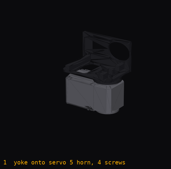
Yoke onto servo 5. The Ø24 boss sits on the horn, the four horn screws go in from above.
-
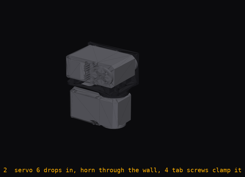
Servo 6 into the yoke. Horn toward the wall, disc into the 22 mm bore, body on the two ribs. Four M2 × 4 self-tap through the wall into the tabs.
-
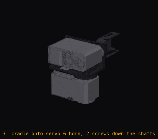
Body onto servo 6. Two M2.5 × 5 down the shafts at ±7 mm, driven through the open top.
-
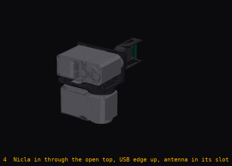
Nicla in, lid on. Board through the lid face, USB edge toward the open top, lens out; it slides under the two lips. Lens through the cone, ToF in the window, press the lid until it clicks. No screws.
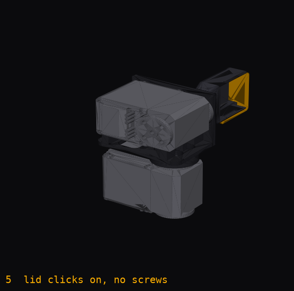
-
Power and calibrate. Micro-USB from the arm's supply, cable along the servo bus. Then
strands-arm calibrate.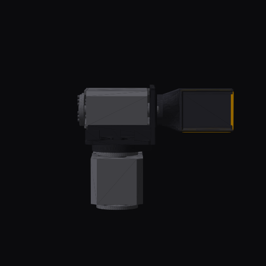
Screws
Horn joints take M2.5 × 5 only: the thread is 2.5 mm deep behind a 3 mm flange. Longer screws bottom out early.
What done feels like
The board slides in by hand. Servo 6 drops into the yoke with no force and does not rock. The lid clicks once; the USB sits 0.31 mm proud so the cable seats. Tilt clears the yoke by 9.74 mm over its full mechanical ±90°; the guard uses ±60°.
Every fit is measured against STS3215_03a.step and NiclaVision.step by hardware/cad/fitcheck_*.py. Next: calibrate.